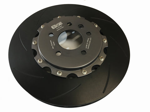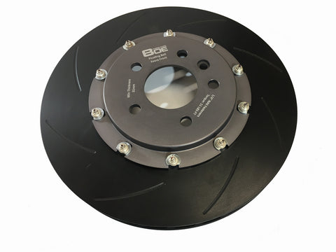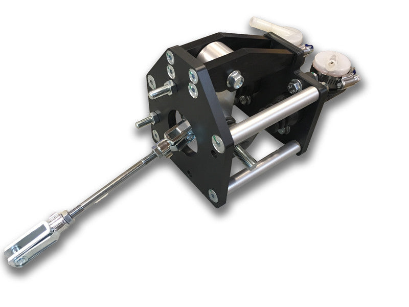


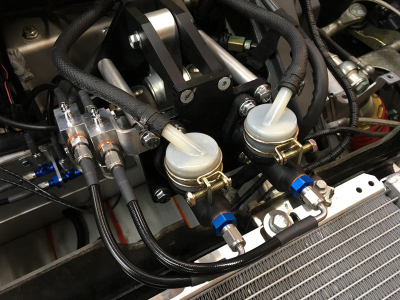

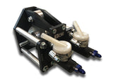
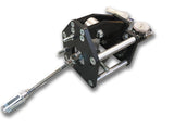
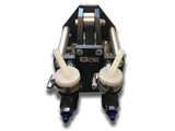

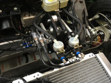
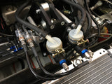
Brake Bias Cage
$ 1,449.00
Details
Perhaps one of the most transformative modifications you can make to the Lotus Elise/Exige/211 platform is in the brakes. While the steering and suspension is nearly telepathic on the Lotus, the brakes are numb, terribly biased to the front, and provide unstable to braking on the street, track, and autocross course.
Our drivers are telling us our Bias Cage is the single best mod they've made to the car!
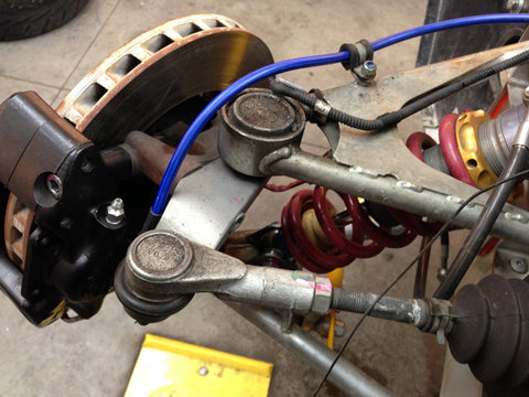
- Essentially plug and play
- Dual Tilton Master Cylinders, Front and Rear
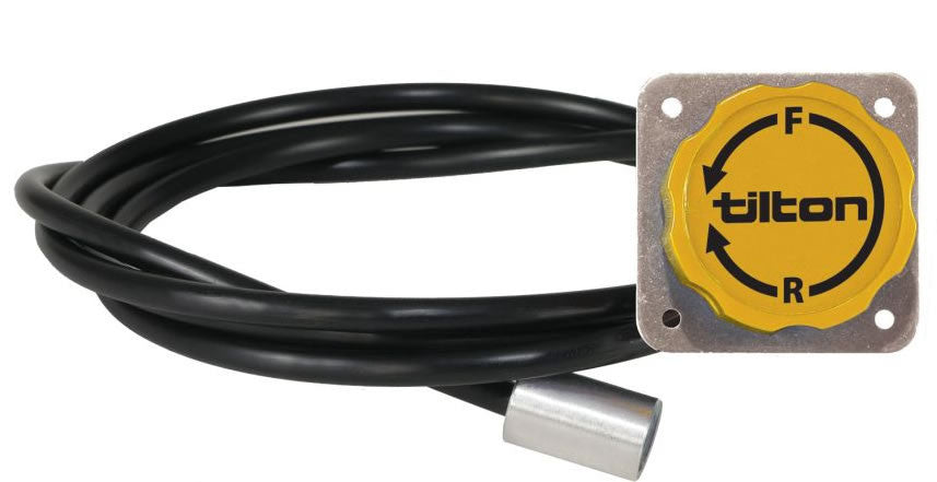
- Remote, In-Cabin Tilton Bias Adjuster
- CAD Designed at BOE. Track, street, and autocrossed tested!
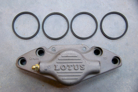
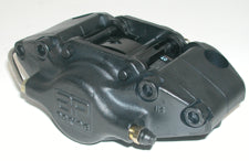
- Compatible with stock and all aftermarket calipers
- Allows for nearly infinite front to rear brake bias
- Anodized 6061-T6 aluminum construction
- Oversized and supported transfer beams and bushings for extremely rigid and the most consistent performance for each application of the brake pedal
- Used by some of the fastest road course and autocrossed Lotus cars on the planet
- Eliminates the brake booster
- Eliminates the ABS, but can be fashioned to work with the stock ABS or a Bosch Motorsports ABS
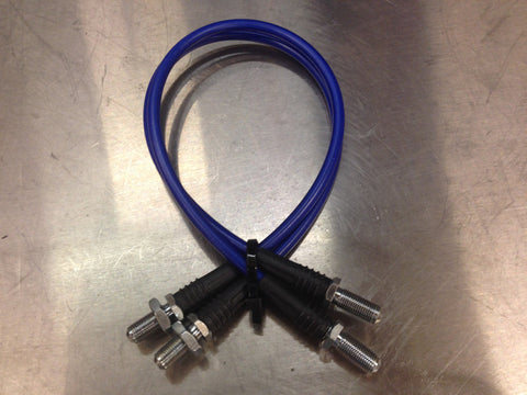
- Offered with and without BMRS plumbing and sensor fittings
- No more ice mode
More info on Brake Bias
Brake Bias and Performance
Why Brake Balance Matters
by Tom McCready and James Walker, Jr. of scR motorsports
Long, long ago in a magazine far, far away, a few renegade brake engineers rallied together to bring forward the following message:
“You can take this one to the bank. Regardless of your huge rotor diameter, brake pedal ratio, magic brake pad material, or number of pistons in your calipers, your maximum deceleration is limited every time by the tire to road interface. That is the point of this whole article. Your brakes do not stop your car. Your tires do stop the car. So while changes to different parts of the brake system may affect certain characteristics or traits of the system behavior, using stickier tires is ultimately the only sure-fire method of decreasing stopping distances.”
However, there’s more to the story. Yes the tires stop the car, but improper brake balance can make a complete mess out of even the best components.
There’s always a “but”, isn’t there?
In order to demonstrate the concept of proper brake balance, it is usually simpler to analyze a car’s handling characteristics and then apply those principles back to the braking system. (For some unknown reason, people seem to have a much better understanding of handling than they do of braking. Brake guys think that’s not fair, but we’ll try to use it to our advantage here.)
In theory what everyone is looking for is that all-too-elusive handling balance which makes the car corner as fast as it possibly can. Generally speaking, this is referred to as the ‘neutral’ car and takes the driver directly to victory circle following the race. Rarely do we ever hear of a winning driver explaining that the car was a handling nightmare.
Of course, no car is ever perfect, so we have ways of expressing how far from optimal the handling balance really is. When a car enters a corner and the front end skids off into oblivion, this is called understeer – the car is turning less than the driver intends. On the other hand, if the rear end breaks free and begins to lead the car through the corner this is called oversteer – now the car is turning more than the driver intends.
In both cases, when one end of the car breaks traction, or begins to slide, the driver can pretty much bet on the fact that he (or she) has found the maximum cornering speed for that particular corner. Yes, there are a million other factors at play which can govern the handling relationship, but the longer each end of the car can “hold on”, the higher the cornering speeds. Conversely, if one end or the other consistently breaks traction early in the cornering event, corner speeds will suffer dramatically.
Naturally, as speeds continue to increase something has to eventually give and slide; however, the very best suspensions do a great job of ensuring that both ends of the car break traction at relatively the same time. How far one end breaks traction in advance of the other is ultimately a function of driver preference (this is just one reason why there is no single “perfect” set-up), but if there are complaints of heavy understeer or terminal oversteer you can rest assured that one end of the car is three steps farther ahead than the other.
Umm…isn’t this an article about brakes?
So, now that we are all chassis tuning experts, let’s look at how this information can be used to understand our braking system. Grab a pop and a bag of chips and hang on.
Like the corner carvers, the brake guys are always looking to achieve maximum accelerations, but of course these accelerations are now really decelerations. Stopping distance is everything and every single foot counts. Remember: outbraking your opponent by just two feet every lap for a twenty lap sprint race can result in a three to four car length advantage at the checkered flag. Attention to detail matters.
As braking force is continuously increased, one end of the car must eventually break traction. If the front wheels lock up and turn into little piles of molten rubber first we say that the car is “front biased”, as the front tires are the limiting factor for deceleration. In the not-so-desirable situation where the rear tires are the first to lock we say that the car is “rear biased”, but the driver would probably have a few more choice adjectives to add. In either case, however, one end of the car has given up before the other, limiting the ultimate deceleration capability of the car.
Just like the car that pushes its way through corners all day long, a car which is heavily front biased will be slow and frustrating, but relatively easy and benign to drive. On the other hand, like the oversteer monster that people are afraid to even drive around the paddock, a car which is severely rear biased will be a scary, twitchy ride resulting in a bad case of the white-knuckle syndrome. Envision an imaginary co-pilot yanking up on the park brake handle in the middle of every corner, and you begin to get the idea. While a rush to drive at speed, it will be horribly slow on the stopwatch.
The car with perfectly balanced brake bias will, however, be the last one to hit the brakes going down the back straight. By distributing the braking forces so that all four tires are simultaneously generating their maximum deceleration, stopping distance will be minimized and our hero will quickly find his way to victory lane. Just like neutral handling, balanced brake bias is our ticket to lower lap times.
All that said, once the braking system has achieved its perfect balance, it is still up to the tires to generate the braking forces. It’s still the tires that are stopping the car, but a poorly designed braking system can lengthen stopping distances significantly, expensive sticky tires or not.
So why is brake biasing necessary?
The maximum braking force that a particular tire can generate is theoretically equal to the coefficient of friction of the tire-road interface multiplied by the amount of weight being supported by that corner of the car. For example, a tire supporting 500 pounds of vehicle weight with a peak tire-road coefficient of 0.8 (a typical street tire value) could generate, in theory, 400 pounds of braking force. Throw on a good race tire with a peak coefficient of 1.5, and the maximum rises to 750 pounds of braking force. More braking force means higher deceleration, so we again see the mathematical benefits of a sticky race tire.
On the other hand, if our race tire was now only supporting 300 pounds, the maximum force would drop from 750 pounds of braking force to 450 pounds of braking force – a reduction of 40%.
Since the amount of braking force generated by the tire is directionally proportional to the torque generated by the calipers, pads, and rotors, one could also say that reducing the weight on the tire reduces the maximum brake torque sustainable by that corner before lock-up occurs. In the example above, if an assumed 700 ft-lb. of brake torque is required to lock up a wheel supporting 500 pounds, then only 420 ft-lb. (a 40% reduction) would be required to lock up a wheel supporting 300 pounds of vehicle weight.
At first glance, one could surmise that in order to achieve perfect brake bias you could just:
1. Weigh the four corners of the car
2. Design the front and rear brake components to deliver torque in the same ratio as the front-to-rear weight distribution
3. Win races
In other words, for a rear-wheel-drive race car with 50/50 front/rear weight distribution it would appear that the front and rear brakes would need to generate the same amount of torque. At the same time, it would look like a production-based front-wheel-drive car with a 60/40 front/rear weight distribution would need front brakes with 50% more output (torque capability) than the rears because of the extra weight being supported by the nose of the car.
Like most things in life though, calculating brake bias is not as simple as it may appear at first glance. Designing a braking system to these static conditions would neglect the second most important factor in the brake bias equation – the effect of dynamic weight transfer during braking.
The ever-present weight transfer phenomenon
Let’s assume we have a 2500 pound car with a 50/50 static weight distribution. If we are only concerned with the vehicle at rest, it’s easy to determine the weight on each wheel. We just need to find some scales and weigh it. The sum of the front corner weights is equal to the front axle weight (1250 pounds), and the sum of the rear corner weights is equal to the rear axle weight (also 1250 pounds). The weight of the vehicle is of course equal to the sum of the two axle weights (our original 2500 pounds), and this weight can be thought of as acting through
the vehicle’s center of gravity, or CG. Figure 1 sums it up nicely.

Note that when at rest, there are no horizontal (left or right) forces acting on the vehicle. All of the forces are acting in a vertical (up and down) direction. But what happens to the vehicle when we start to apply forces at the tire contact patch to try to stop it? Let’s find out.
During braking, weight is transferred from the rear axle to the front axle. As in cornering where weight is transferred from the inside tires to the outside tires, we can feel this effect on our bodies as we are thrown against the seat belts. Consequently, we now need to add several more arrows to our illustration, but the most important factor is that our CG now has an deceleration acting on it.
Because the deceleration force acts at the CG of the vehicle, and because the CG of the vehicle is located somewhere above the ground, weight will transfer from the rear axle to the front axle in direct proportion to the rate of deceleration. In so many words, this is the effect of weight transfer under braking in living color.
This deceleration force is a function of a mechanical engineer’s most revered equation, F=ma, where F represents the forces acting at the contact patches, m represents the mass of the vehicle, and a represents the acceleration (or in our case, deceleration) of the vehicle. But enough of the engineering mumbo-jumbo – just have a look at these additional factors in Figure 2.

In Figure 3 (the beginning of what we call a “fishbone diagram” – more on this later), we see how our 2500 pound vehicle with 50/50 weight distribution at rest transfers weight based upon deceleration. Under 1.0g of deceleration (and using some typical values for our vehicle geometry) we have removed 600 pounds from the rear axle and added it to the front axle. That means we have transferred almost 50% of the vehicle’s initial rear axle weight to the front axle!

At this point, the brake system we so carefully designed to stop the vehicle with a 50/50 weight distribution is going to apply too much force to the rear brakes, causing them to lock before we’re getting as much work as we could out of the front brakes. Consequently, our hero is going to get that white-knuckled ride we talked about earlier because he creates more tire slip in the rear than the front, and it’s going to take longer for him to stop because the front tires are not applying as much force as they could be.
So what influences brake bias?
If we look at the equations we have developed, we see that all of the following factors will affect the weight on an axle for any given moment in time:
· Weight distribution of the vehicle at rest
· CG height – the higher it is, the more weight gets transferred during a stop
· Wheelbase – the shorter it is, the more weight gets transferred during a stop
We also know from fundamental brake design that the following factors will affect how much brake torque is developed at each corner of the vehicle, and how much of that torque is transferred to the tire contact patch and reacted against the ground:
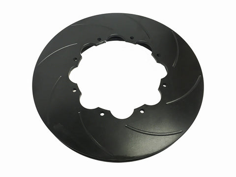
· Rotor effective diameter
· Caliper piston diameter
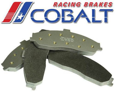
· Lining friction coefficients
· Tire traction coefficient properties
It is the combination of these two functions – braking force at the tire versus weight on that tire – that determine our braking bias. Changing the CG height, wheelbase, or deceleration level will dictate a different force distribution, or bias, requirement for our brake system. Conversely, changing the effectiveness of the front brake components without changing the rear brake effectiveness can also cause our brake bias to change. The following table summarizes how common modifications will swing bias all over the map.
| Factors that will increase front bias | Factors that will increase rear bias | |
| Increased front rotor diameter | Increased rear rotor diameter | |
| Increased front brake pad coefficient of friction | Increased rear brake pad coefficient of friction | |
| Increased front caliper piston diameter(s) | Increased rear caliper piston diameter(s) | |
| Decreased rear rotor diameter | Decreased front rotor diameter | |
| Decreased rear brake pad coefficient of friction | Decreased front brake pad coefficient of friction | |
| Decreased rear caliper piston diameter(s) | Decreased front caliper piston diameter(s) | |
| Lower center of gravity | Higher center of gravity | |
| More weight on rear axle | Less weight on rear axle | |
| Less weight on front axle | More weight on front axle | |
| Less sticky tires (lower deceleration limit) | More sticky tires (higher deceleration limit) |
Perfectly balanced, in theory
While we can do calculations to determine what the optimum front-to-rear brake bias should be under all conditions, the difficult part is creating a brake system that can actually keep up with all of this. Our hero racer has it a little easier than those of us building cars for the real world. If he knows what his maximum deceleration capability is due to the tires he’s using, he can tune his brake system for that specific deceleration level. The good part is, if he tunes his vehicle for this 1.5g decel condition, because of the way weight transfer works, his car will be more front-biased in lower traction conditions, such as rain.
Back to the “fishbone diagram” mentioned earlier. Figure 3 shows front and rear axle weight versus deceleration of the vehicle. Now let’s look at it now as a percentage of the total vehicle weight. We can add on top of this chart the front-to-rear balance of the brake system. For example, if we use the exact same brake components at the front and rear axles of the car, they will each perform 50% of the braking, and the chart will look like Figure 4.

Evaluating this chart, we see that the vehicle will always be rear-biased. That is, the rear brakes will always be applying more force at the tire contact patch than the weight of the rear axle can sustain. This vehicle will always lock the rear brakes before the front. Not so good.
Most cars, however, have brakes at the rear that are smaller than the front. There are a lot of reasons for doing this, and one of them is to help provide the correct brake bias. Also, most cars have a proportioning valve which limits the amount of brake pressure seen at the rear calipers. If we look at the same chart with a more realistic braking system (one that takes into account these effects) it might look like the chart in Figure 5.
FIGURE 5

Perfect brake bias is obtained when the front-to-rear balance of the brake system exactly matches the front-to-rear weight balance of the vehicle. Looking at our typical brake system chart, we see how difficult this is to do. However, if we’re trying to optimize a brake system for a particular deceleration level, it becomes much easier. We can tune the system so that the two lines cross (or come close to it) at the deceleration level the vehicle will be operating at most often. This is easy for a non-aero racing vehicle which typically operates at one fixed deceleration level. For a street car, this is almost impossible to achieve, because a car driven on the street doesn’t always operate at one deceleration level (if yours does, you probably don’t get too many repeat passengers!).
And here’s a free tip – effects of poor brake bias on the street not only include sub-optimal stopping distances, but also include sub-optimal brake pad life. If a car is too heavily front-biased in the deceleration range it typically operates in, it will wear front pads more quickly due to the fact that the rear brakes aren’t doing as much of the stopping work as they could be. However, the rear brake pads will probably last forever…
Perfectly balanced, in practice
Brake bias can be measured in several ways. One method – the way the auto manufacturers do it – is to actually mount wheels on the vehicle that are equipped with strain gages, so that the actual torque at each wheel can be measured throughout a stopping event. Analysis of the vehicle deceleration data combined with the measured torque values and knowledge of the vehicle parameters mentioned above (wheelbase, CG height, weight on each axle at rest) allow us to calculate brake bias for that particular event. This is the most precise method of measuring brake bias. However, there are simpler and cheaper methods that can be just as effective.
We know where most auto manufacturers tune brake bias – they like our cars to be front-biased in all conditions achievable by the tires offered on the vehicle. This helps to insure vehicle stability under braking by the mass public. If we measure stopping distance of the vehicle as delivered from the showroom floor, we have a good benchmark for a vehicle with a 5% to 10% front brake bias.
Now, if we make changes to the car that can effect brake bias and re-measure stopping distance, we can tell immediately if we have taken a step in the wrong direction. For example, it is not uncommon to install more aggressive front brake pads (which will make the car even more front biased) and see stopping distances go up 5% or more. Dedicated race pads can result in even longer stopping distances.
The most dramatic front-bias impacts are usually brought about by “big brake kits” which are not properly matched to the intended vehicle. Any time that a bigger front rotor is installed, there is a simultaneous need to decrease the effective clamping force of the caliper (installing smaller pistons is the easiest method) to offset the increased torque created by larger rotor effective radius. The objective is to maintain a constant amount of brake corner output (torque) for a given brake line pressure as Figure 6 illustrates. Unfortunately, too many upgrades do not take this factor into account, and those poor cars end up with both bigger rotors and larger pistons which serve to drastically shift the bias even more forward. While rock-solid stable under braking, stopping distances will go up dramatically.
This is exactly the reason why StopTech performs instrumented testing for every single kit and application they develop. You’re not just buying parts – you’re also buying the assurance that the brake bias has been developed and tested to be optimized for your exact application.

The flip side can be seen by making changes to increase the amount of rear bias. Because the auto manufacturers leave a little bit of wiggle room in their designs, it is usually possible to make small changes to increase rear bias and end up with shorter stopping distances than stock. Keep in mind, however, that there is only so much of this wiggle room to play with. After a point, increased rear bias will make the car unstable under hard braking and will consequently drive the stopping distances through the roof.
The moral of the story
So, what have we learned? As Figure 7 illustrates, every car has a “sweet spot” for brake bias which will generate the shortest stopping distances possible. Typically, the auto manufacturers design their cars to be 5% to 10% more front-biased than optimum for maximum deceleration, but they provide enhanced brake stability in return. Not a bad trade-off for the public at large, and not necessarily a bad place for a race car in the heat of battle either.
As you go about modifying your car for the street or for the track, be aware that changes in the braking system as well as changes in the car’s ride height, weight distribution, or physical dimensions can swing brake bias all over the place. The only sure-fire way on knowing if your final bias has been optimized is to measure stopping distance both before and after your modification(s).
In summary, your tires certainly still stop the car, but if your bias is out in left field you might not be able to use everything they have to offer. Your braking system is just that – a system – and keeping an eye on brake bias effects during modification will go a long, long way toward bringing home the checkered flag. Of course, selecting the proper kit from a manufacturer who has already done the hard part for you can make the trip to victory lane that much easier…